
February 2013
POV Pong Game
I started this project because I had just finished my LOGO Robot and I wanted to do some more PIC programming. I had never built a persistence of vision (POV) display and I had never programmed a pong game before, both things I think every maker should do once in their life. So I decide to check off two things at once and build this little game.  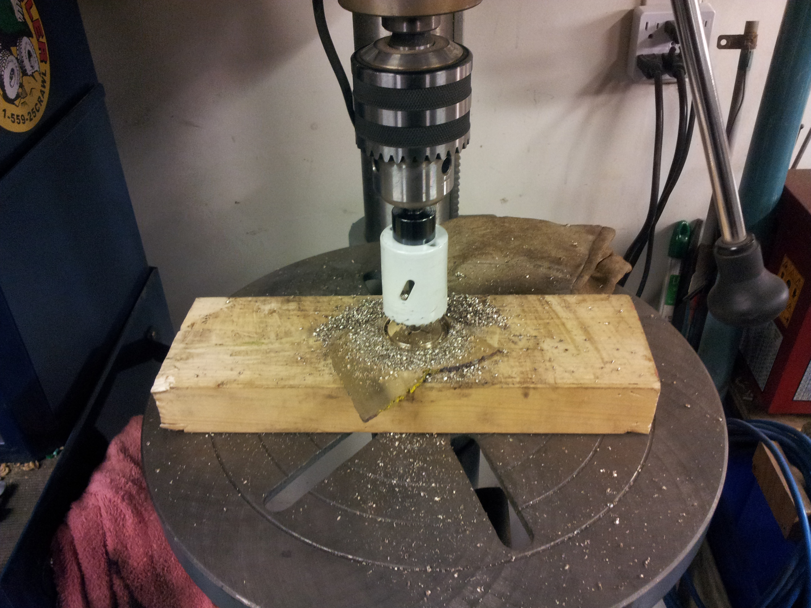 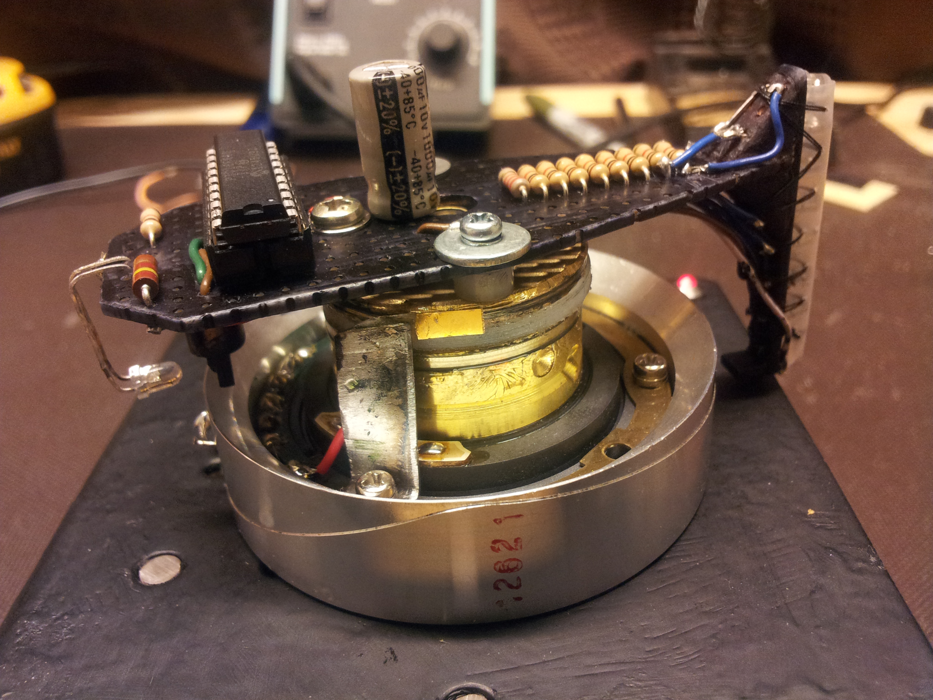
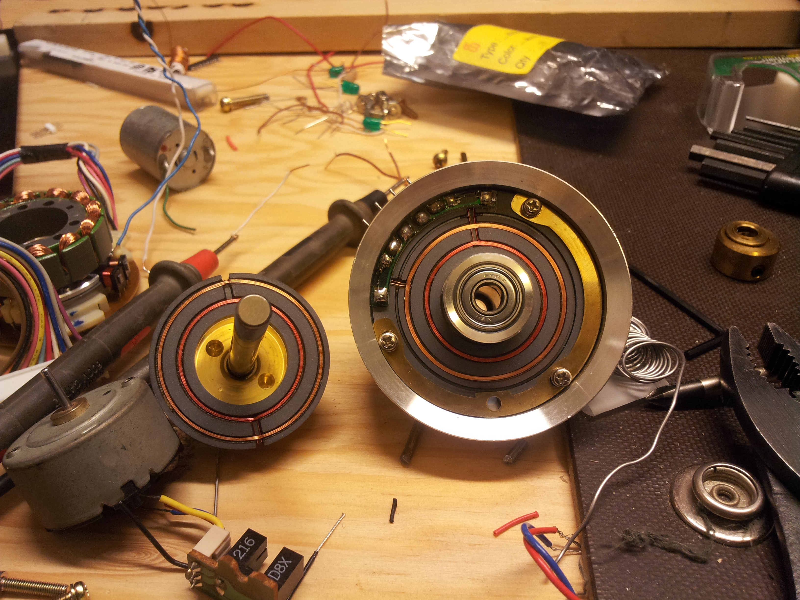
I started with an old VCR head and went looking for a suitable small DC motor. I found one that would work with the limited pullies I had available. I enjoy the challenge of building something with only the things I had on hand. It made for a more interesting build. The next thing I wanted to get out of the way was the slip rings and brushes to bring power to the rotating circuit board. I had a 1/8" slice of brass that I used to make the positive upper slip ring. I used a hole saw to get the rough shape and then cleaned it up on my mini lathe. I drilled and bored a hole to fit over the top of the VCR head. I also made an insulator out of some HDPE plastic on my lathe. The bottom negative slip ring is just a part of the VCR head. I made the brushes out of an old micro switch. I separated the two springy copper pieces that touch together (when closed) and made each of them a brush. Then I solder the negative brush onto a custom bracket I made and the positive one I epoxied to another custom bracket(picture above right). When everything was glued and bolted down I could fine tune the brackets by bending them with a pair of pliers. 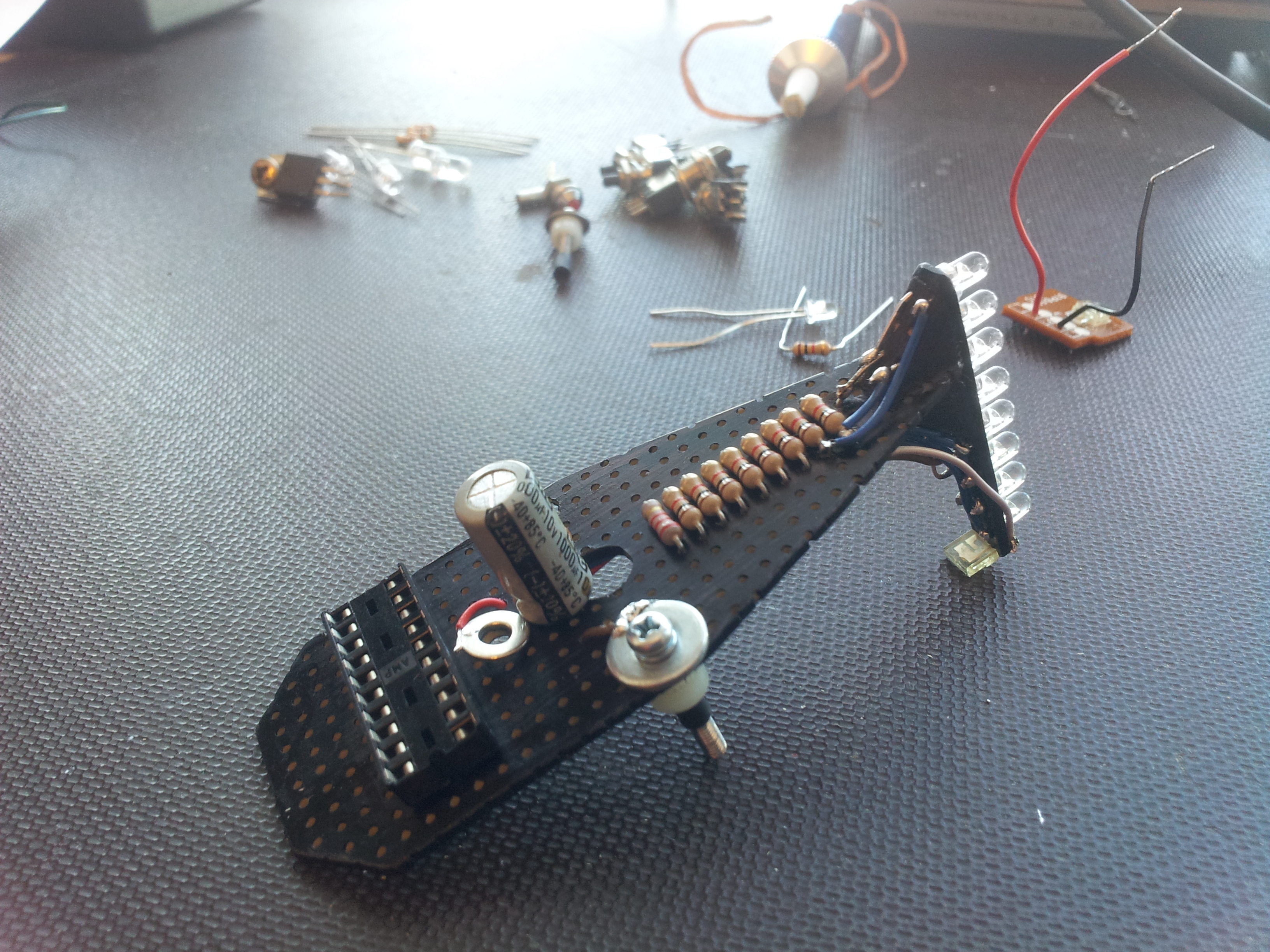 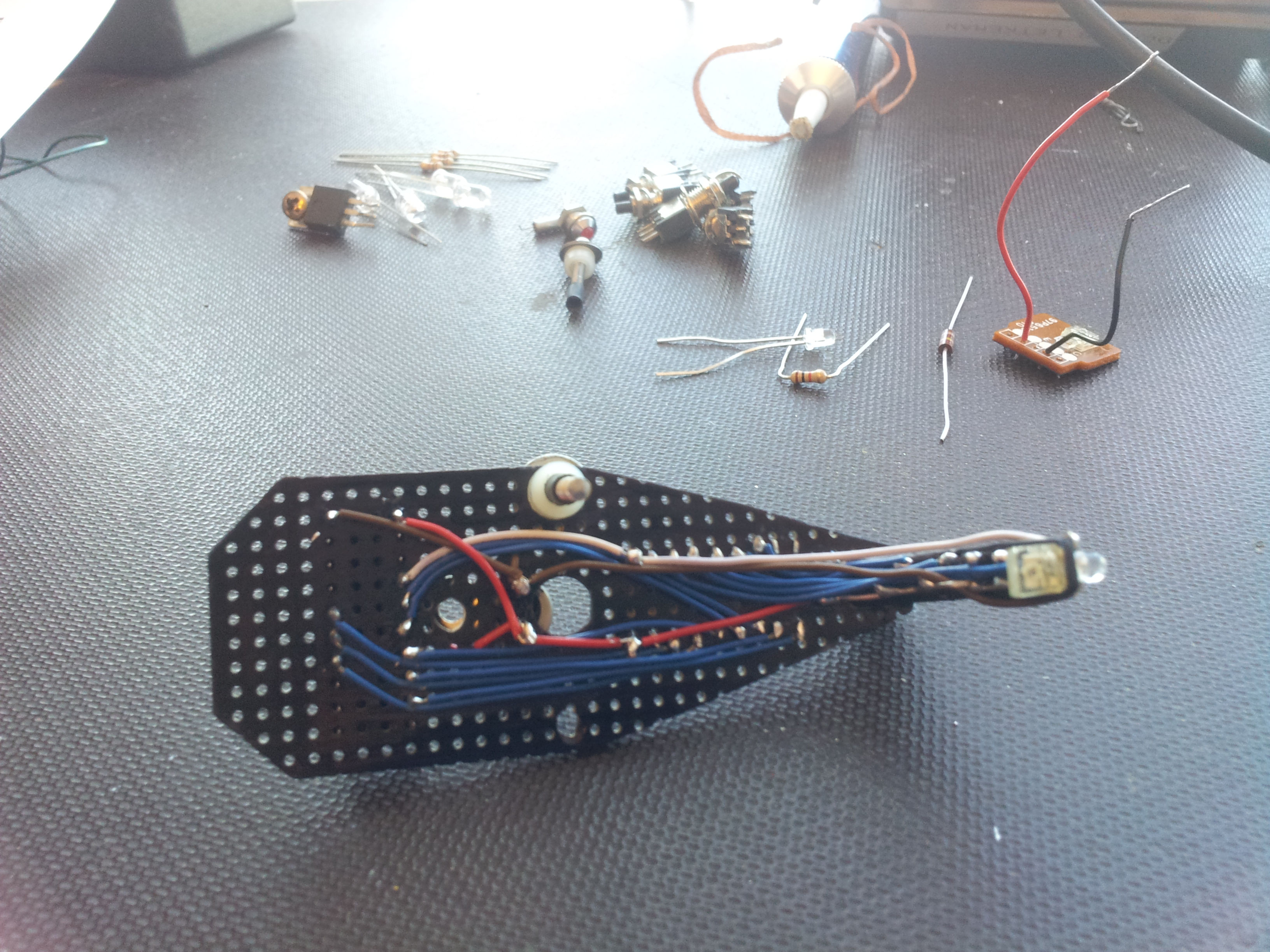 
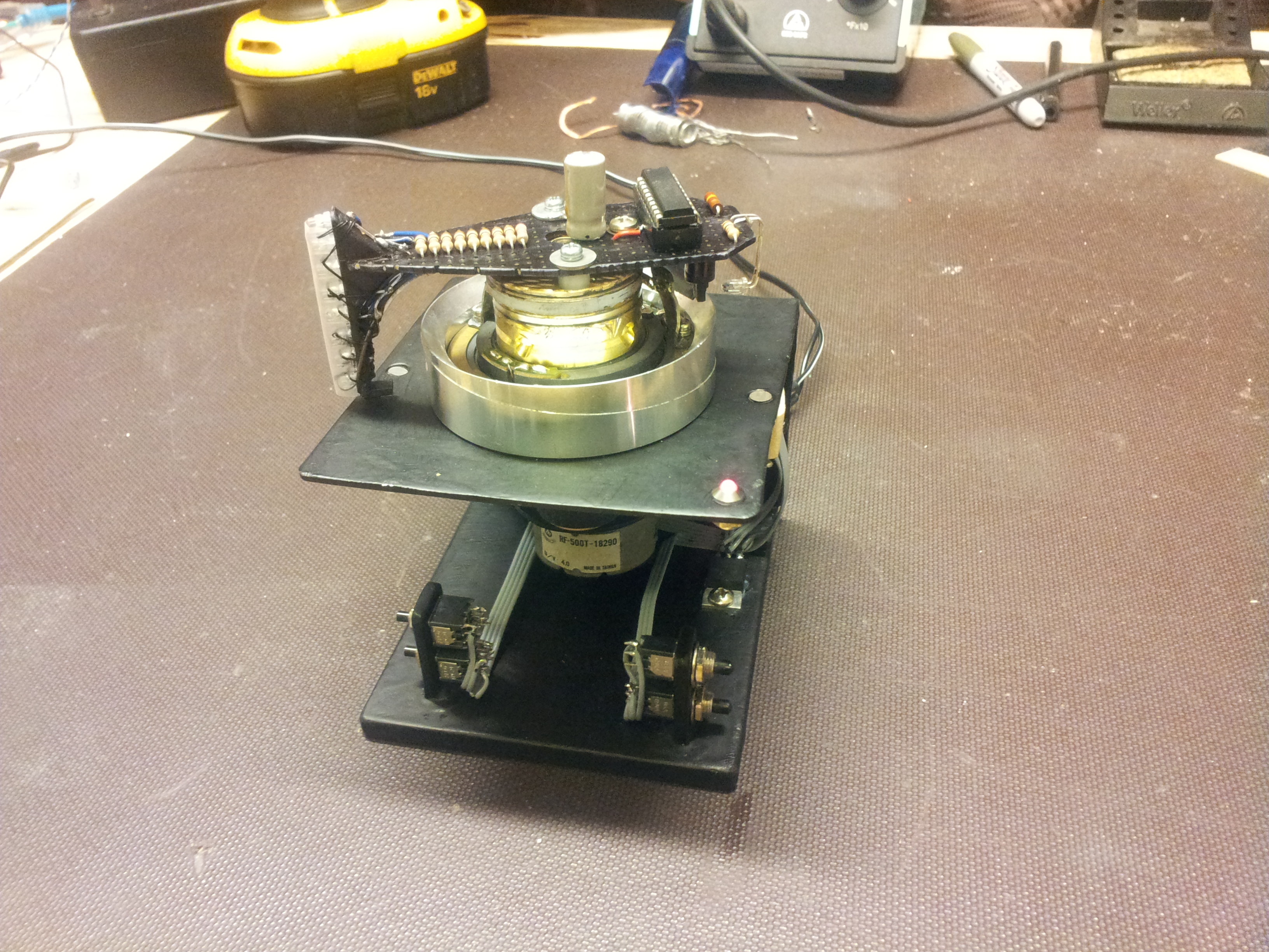
With the hard part done I designed and built a frame out of sheet steel. The base is 1/4" with some 1/8" welded to the back where the 1/16" bracket bolts on. The bracket holds the VCR head, motor, and input LEDs. 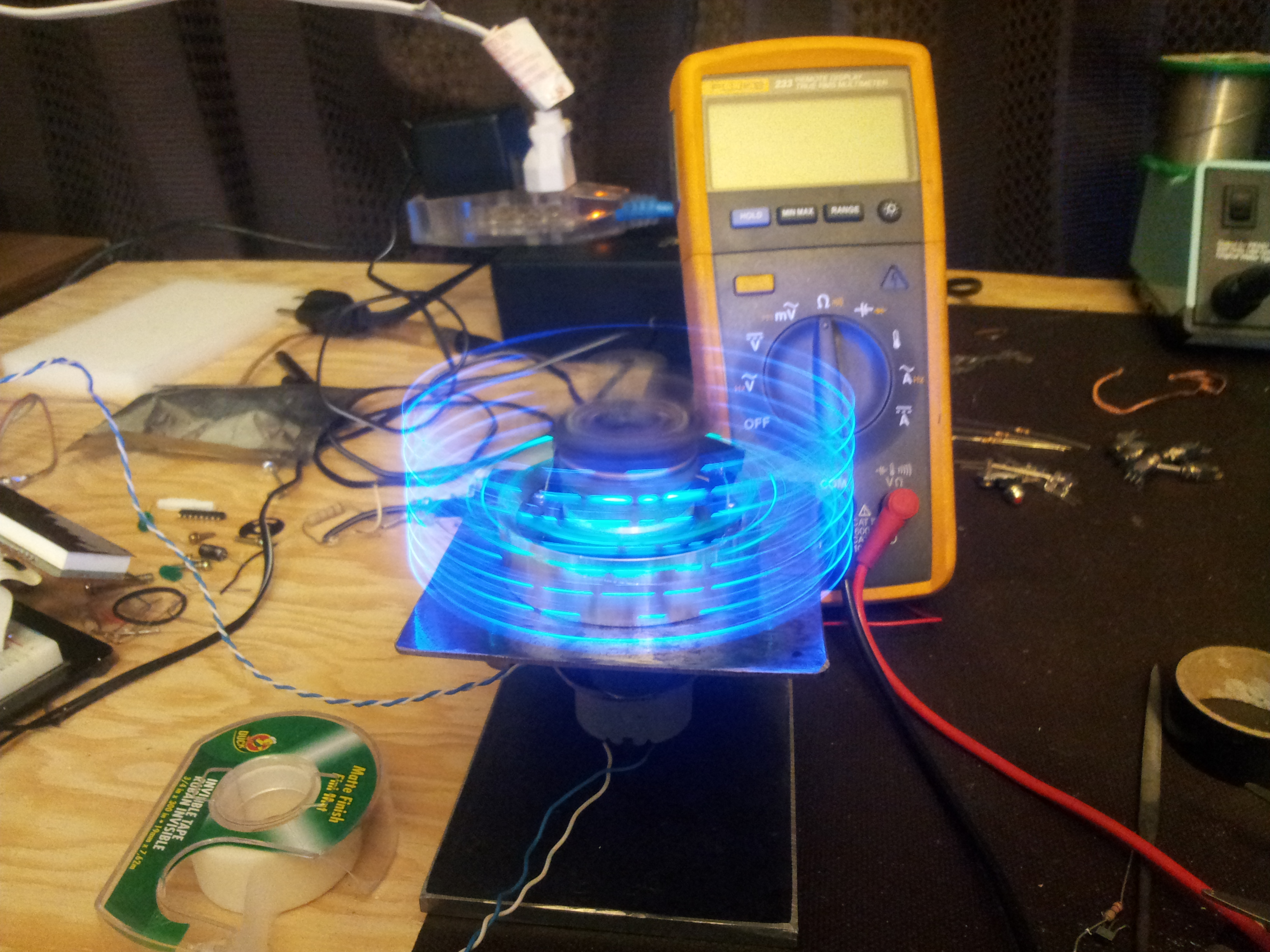 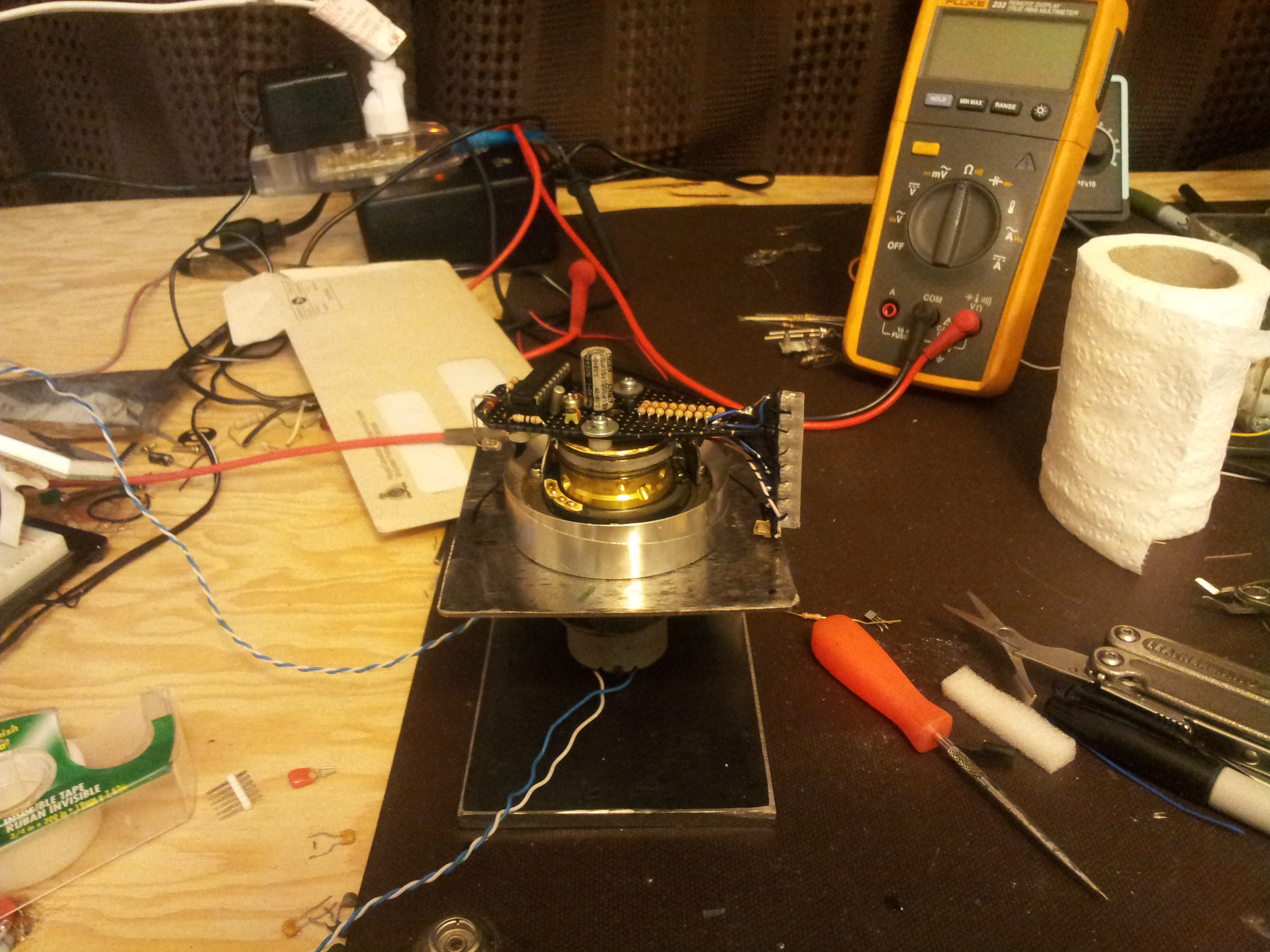 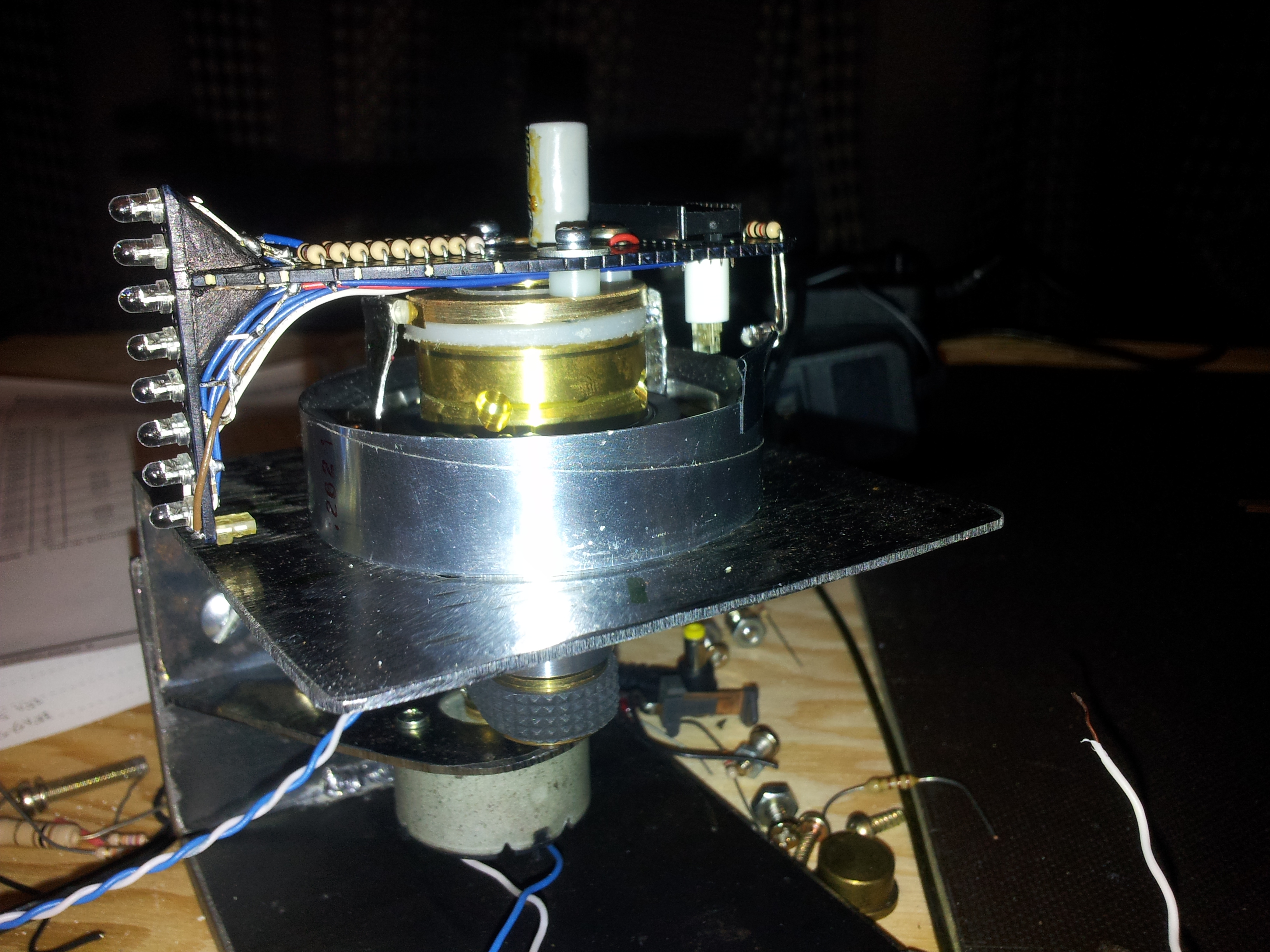
I wanted to get the button information up to the spinning board without using a bunch of brushes. I decided to use white LEDs in the base and a phototransistor on the main board. The phototransistor is mounted to the bottom of the display LED stack and scans over the white input LEDs as the board spins. If an input LED is on it will generate an external interrupt. In the interrupt service routine in checks the value of timer1 and depending on the value it will know what LED (and thus button) is active. Timer1 is reset every period. To sync the display to the motor I use a green LED pointed at another phototransistor. Ever cycle the light gets interrupted by a piece of electrical tape taped to the edge of the VCR head base. This circuit is what regulates the main function in the PIC. The photo transistors are very easy to use. the ones I had were from something I took apart in the past, most likely a VCR. I used a 2.2k ohm resistor between the collector of the phototransistor and Vcc and the emitter went to ground. This way I didn't need any interface circuit between it and the PIC. When there was no light is the collector was +5VDC and when there was light is was pulled down to 0.7VDC which is good enough for a logic zero for the PIC.  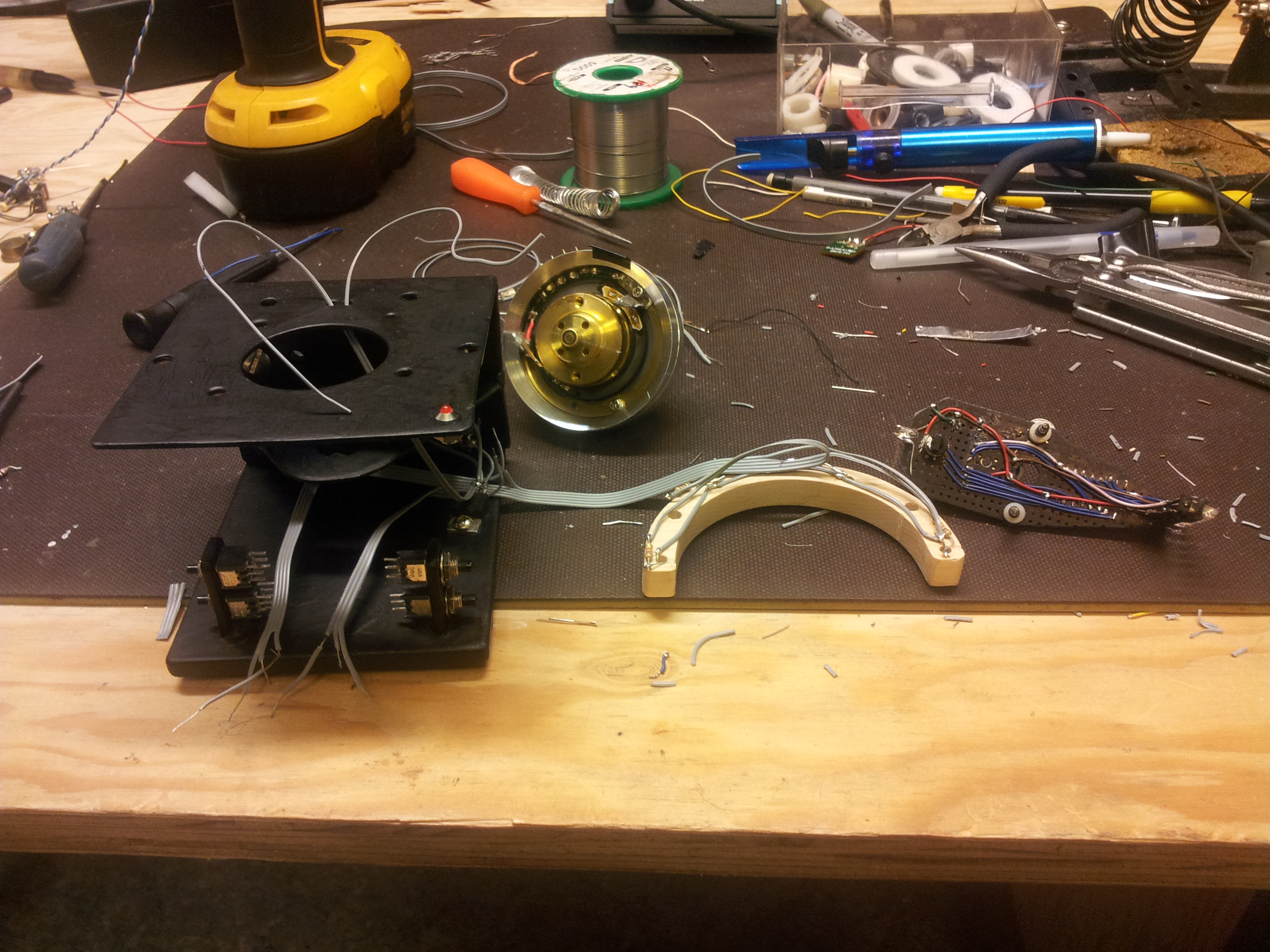 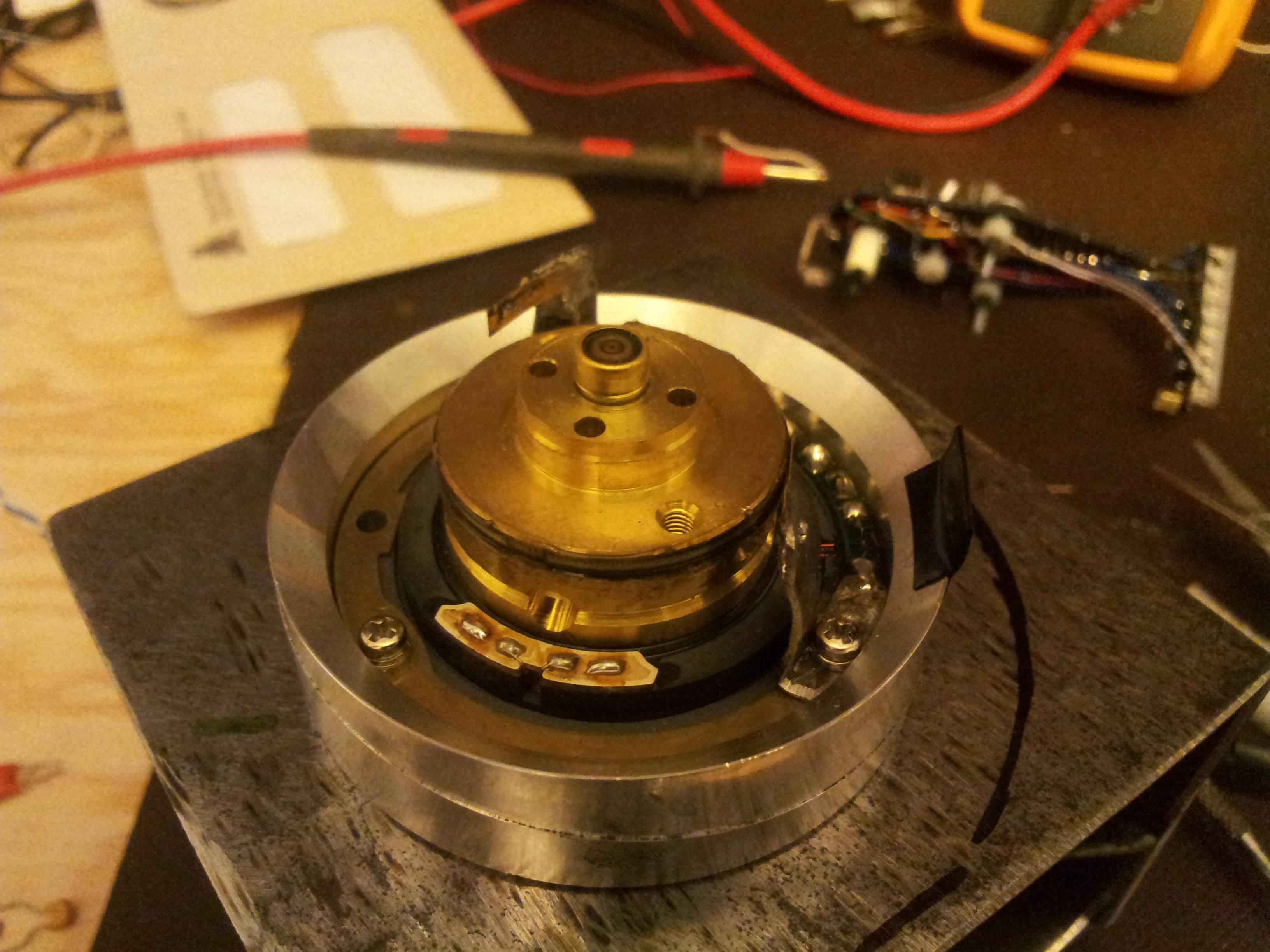
The display LEDs are current limited with 1k ohm resistors. I secured a piece of wax paper in front of the LED stack to defuse the light a little and give the pixels a little more vertical size. I mounted an LED to the frame in the top right so I know when it's plugged in. The LED is lit weather or not the power switch in on. The push button switches for the input are mounted to some 1/8" welded to the base. They're wired to the white LEDs with some 1k ohm resistors. The input LEDs are mounted to the underside of the top bracket with a wooden bracket. A barrel jack and power switch mounted to the back peice of 1/8" finishing off the physical build. 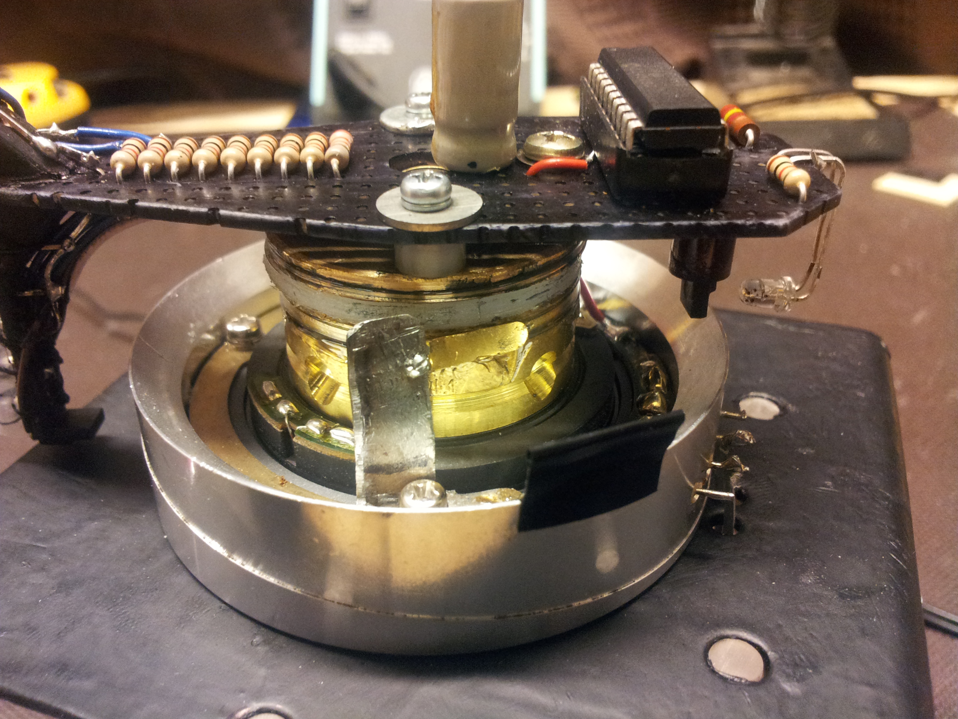  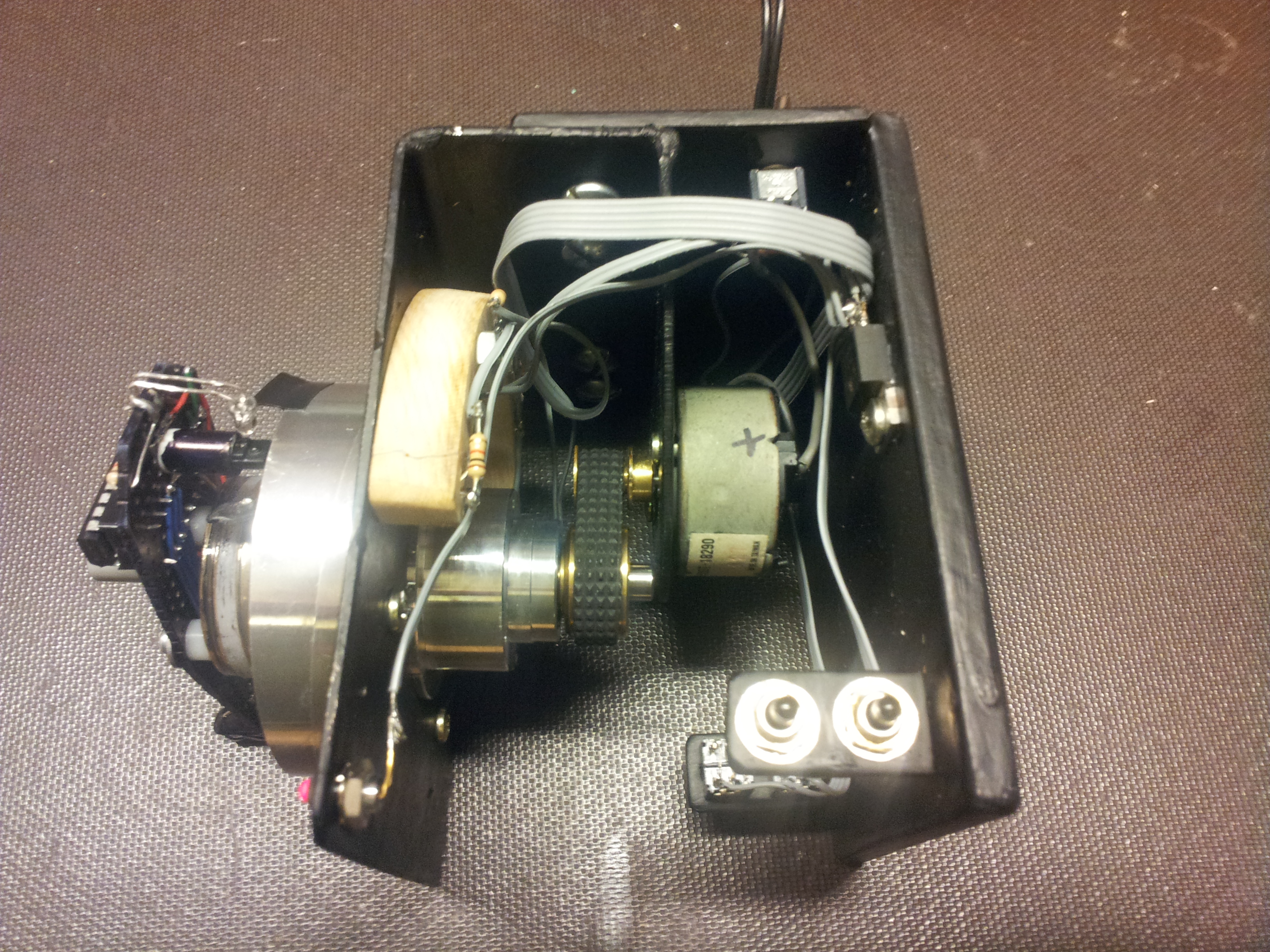
The program took some effort. Some of the features I was using on the PIC I had never used before. I had to do some reading in the datasheet to get everything to work. I wrote the c code in 'Kate' text editor for Linux and compiled the source with sdcc. I then used pk2cmd to write the hex file to the PIC with the help of my PicKit2. Here is the source code (two files) and hex file for anyone who's interested. A picture of the schematic is below. 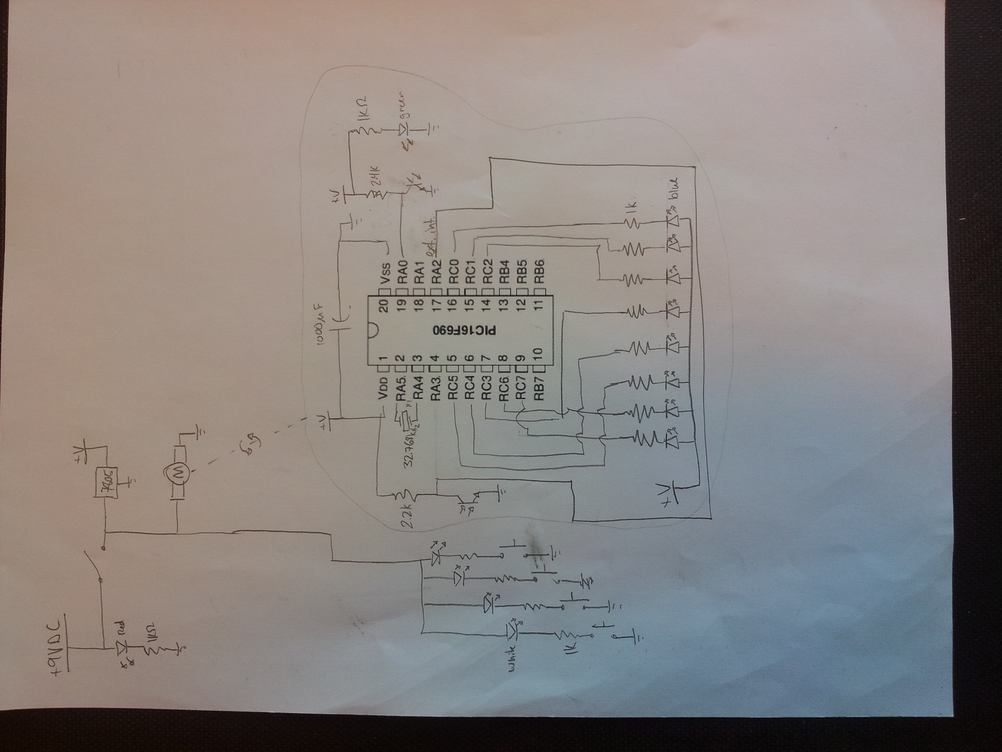
|

